of the free-turbine outer case, inner front and rear case, four hollow struts and their Outer shrouds,
twelve exhaust struts, and the No. 4 bearing housing. Housed in the case are the free-power turbine
second-stage rotor, No. 4 bearing oil nozzle, and free turbine accessory drive gear and shaft assembly,
item 20 in figure 8.2.
8.7.
TURBINE EXHAUST DUCT
The free-turbine shaft and shaft cases are housed in the exhaust duct. The exhaust duct
assembly consists of inner and outer assemblies, stiffeners, exhaust duct ring, and front and rear flanges.
The exhaust duct bolts to the free-turbine case rear flange.
8.8.
MAIN BEARINGS
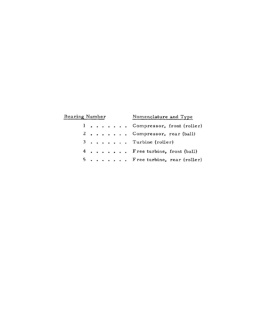
All references to main bearings in this chapter are made by bearing number rather than by
bearing nomenclature. Here are the bearing numbers with their corresponding nomenclatures and types.
8.9.
ENGINE FUEL SYSTEM
The T-73 is equipped with a single-element, centrifugal-boost fuel pump. The pump is
mounted on and driven by the component-drive gearbox. On the rear of the pump is a mounting pad
for the engine fuel control. The fuel boost pump raises the fuel pressure by approximately 20 psi. Fuel
then passes through an externally mounted fuel de-icing heater. From the de-icing heater, fuel returns to
the pumps at the inlet fuel filter and is directed to the main pumping element. The main pumping
element raises the pressure to approximately 800 psi, and fuel passes out of the pump to the engine fuel
control.
The fuel control is a hydromechanical control designed to meter fuel to the engine. The
control has a fuel metering system and a computing system. The metering system, subject to engine
operating limitations, selects the rate of fuel flow supplied to the
218


 Previous Page
