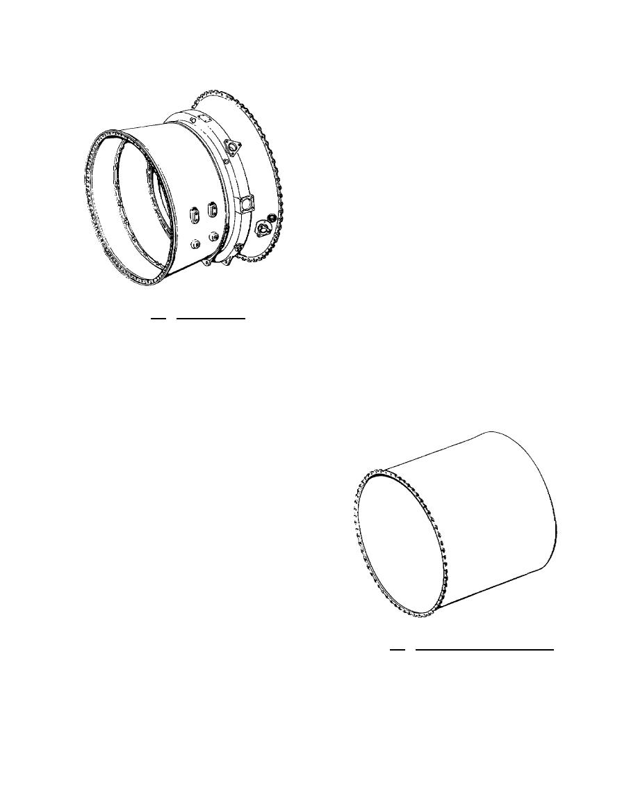
The diffuser case, illustrated in figure 8.5, is a welded steel assembly located between the
compressor inlet case and the combustion chamber case. It consists of an inner and outer case and 8
hollow struts. It houses stages 5 through 9 of the
compressor rotor shroud and vane assembly, the
9th stage exit guide vanes, and No. 2 main
bearing and seal.
The diffuser assembly reduces air
velocity and increases air pressure for entry into
the combustion chambers. High pressure air
from this case is bled off for anti-icing, fuel
heating, and bearing pressurizing.
Figure 8.5. Diffuser Case.
On the outer case at the 3 and 9 o'clock positions are the engine mount pads. At the bottom
of the case are bosses for installing the gearbox and the fuel-pressurizing dump valve.
8.4.
COMBUSTION SECTION
The combustion chamber case is bolted between the diffuser case and the free turbine case.
This combustion chamber outer case, shown in figure 8.6, forms the outer rigid support member of the
engine and must be removed for completing a hot
section inspection.
Located within the
combustion outer case are eight combustion
chambers (cans), the combustion inner case, fuel
manifolds, and the combustion chamber outlet
duct. The combustion chambers are attached by
clamps to the combustion chamber outlet duct in
the aft end of the combustion chamber case.
Flame tubes interconnect all combustion
chambers. Chambers three and six have igniter
plug cutouts.
Each combustion chamber,
illustrated in
Figure 8.6. Combustion Chamber Case.
215


 Previous Page
