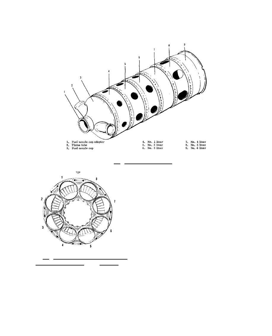
figure 8.7, consists of six liners, a fuel nozzle cap, a fuel nozzle cup adapter, and male or female flame
tubes.
Figure 8.7. Combustion Chamber.
The combustion chamber outlet duct,
shown in figure 8.8, acts as a transition area to
combine the gas flow from the eight combustion
chambers and introduce it into the first stage
nozzle vanes.
The fuel manifold consists of a
secondary manifold within the primary manifold.
Eight duplex fuel nozzles, one for each
combustion chamber, are placed around the fuel
manifold. Each nozzle has a primary orifice and
a secondary orifice. Fuel sprays from the primary
orifice during low pressure and from both orifices
at high pressure. Fuel strainers in the primary
and
Figure 8.8. Combustion Chamber Outlet Duct
and Combustor (Can)
Positions.
216


 Previous Page
