9.8.
EXHAUST DUCT
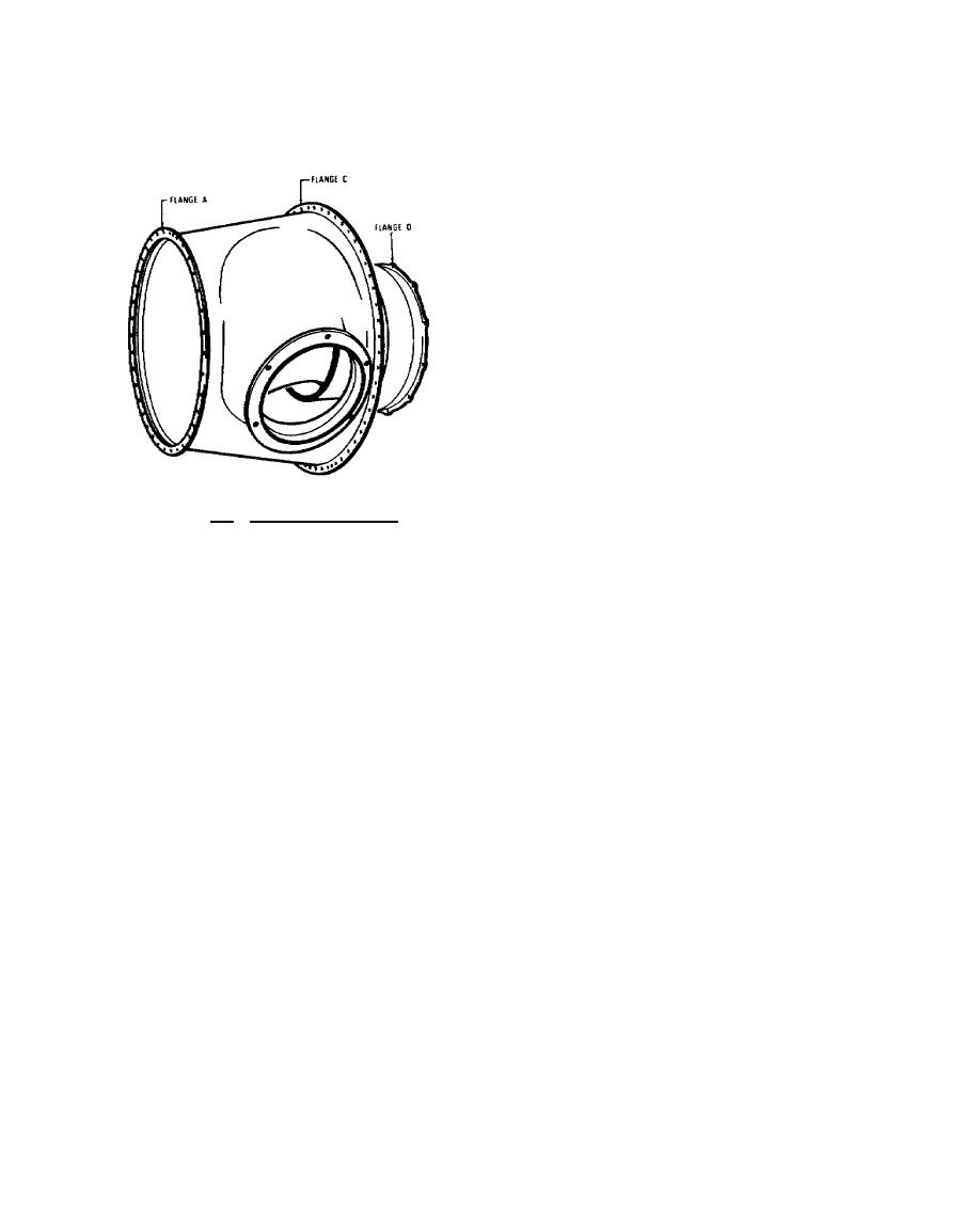
The exhaust duct shown in figure 9.8 consists of a divergent, heat-resistant steel duct
provided with two outlet ports, one on each side of the case. The duct is attached to the front flange of
the gas generator case and consists of inner and
outer sections. The outer conical section, which
has two flanged exhaust outlet ports, forms the
outer gas path and also functions as a structural
member to support the reduction gearbox. The
inner section forms the inner gas path and
provides a compartment for the reduction gearbox
rear case and the power turbine support housing.
A removable sandwich-type heat shield insulates
the rear case and support housing from the hot
exhaust gases. A drain passage located at the 6
o'clock position at flange C leads to the gas
generator case. This automatically drains the
exhaust duct of any fluid accumulated during
engine shutdown through the front drain valve on
the gas generator case.
Figure 9.8. Exhaust Duct, -702.
9.9.
REDUCTION GEARBOX
Located at the front of the engine is the reduction gearbox, which consists of two
magnesium alloy castings bolted to the front flange of the exhaust duct. A cross-section view of the
reduction gearbox is illustrated in figure 9.9.
The first stage of reduction is contained in the rear case. Torque from the power turbine is
transmitted through the power turbine shaft to the first stage sun gear. The spur-gear end of the sun
gear drives the three planetary gears in the first stage planet carrier. The first stage ring gear is located in
helical splines in the rear case assembly. The torque developed by the power turbine is transmitted
through the sun gear and planet gears to the ring gear. This results in rotation of the planetary carrier.
The ring gear, though secured by the helical splines, is allowed to move axially between the case and
three retaining plates. This movement is used in the torquemeter located inside the rear gearbox
assembly, which is discussed in paragraph 9.16.
235


 Previous Page
