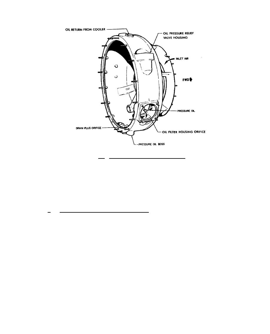
Figure 9.5. Compressor Inlet Case, -700 Engine.
The No. 1 bearing support is contained within the compressor inlet case centerbore. A
conical tube is fitted in the centerbore of the oil tank compartment to provide a passage for the coupling
shaft which extends the compressor drive to the accessories mounted on the rear accessory case. The
pressure oil pump, driven by an accessory drive gear, is located in the bottom of the oil tank. The
pressure oil relief valve and main oil filter, with check valve and bypass valve assemblies; are located on
the right side of the inlet case at the 1 and 3 o'clock positions, respectively.
b.
The compressor rotor and stator assembly, shown in figure 9.6, consists of a three-stage
axial rotor, three interstage spacers, three stator assemblies, and a single-stage centrifugal impeller and
housing. The compressor blades are made of stainless steel and attached, with limited clearance, to the
compressor hub in dovetail grooves. This accounts for the metallic clicking heard during compressor
run-down. Axial movement of compressor blades is limited by the interstage spacers located between
the disks. The first stage compressor blade airfoil differs from those in the second and third stages
which are identical. All three stages differ in
230


 Previous Page
