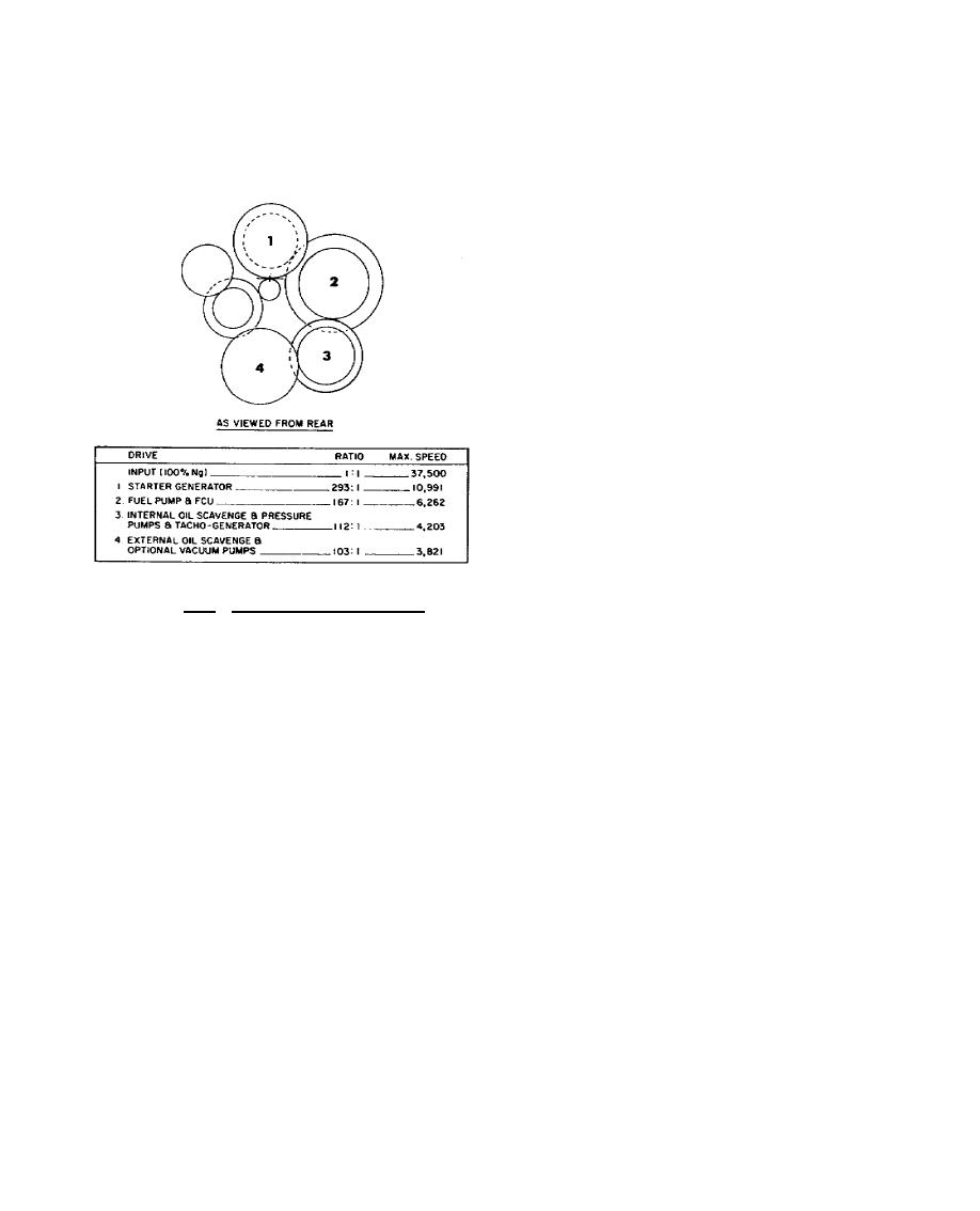
The rear casting forms an accessory gearbox cover with support bosses for the accessory drive
bearings and seals. The internal scavenge oil pump is secured inside the housing, and a second scavenge
pump is externally mounted. Mounting pads and studs are located on the rear face for the combined
starter-generator, the fuel control unit with the sandwich-mounted fuel pump, and the N1 tachometer-
generator. Three additional pads are available for optional requirements; see figure 9.11.
An oil tank filler cap and dipstick are located at
the eleven o'clock position on the rear housing.
A centrifugal oil separator mounted on the starter-
generator's drive gearshaft separates the oil from
the engine breather air in the accessory gearbox
housing.
9.11.
BEARING INSTALLATION
The compressor rotor assembly is
supported and secured in the rear section of the
gas generator case by two bearings. The outer
race of No. 1 ball bearing is held in its flexible
housings by a special nut and keywasher. The
split inner race, spacer, and rotor seal are stacked
against a shoulder on the compressor rear hub
shaft and secured by a cup-washer and special
nut. The outer flange of the No. 2 roller bearing
is attached to the gas generator centerbore by four
Figure 9.11. Accessory Gearbox Train.
bolts and tablock washers.
The compressor turbine disk holds the plain inner race stacked in position between front and
rear rotor seals on the compressor front stubshaft and a shoulder on the stubshaft. The bearing
installation of the T74 engine is illustrated in figure 9.12.
The power turbine disk and shaft assembly is supported and secured in the power turbine
shaft housing by the No. 3 and No. 4 bearings. Bearing No. 3 is a roller type, and No. 4 is a ball type.
238


 Previous Page
