permits compressor air to bleed off and allows a
more rapid acceleration.
The pneumatic
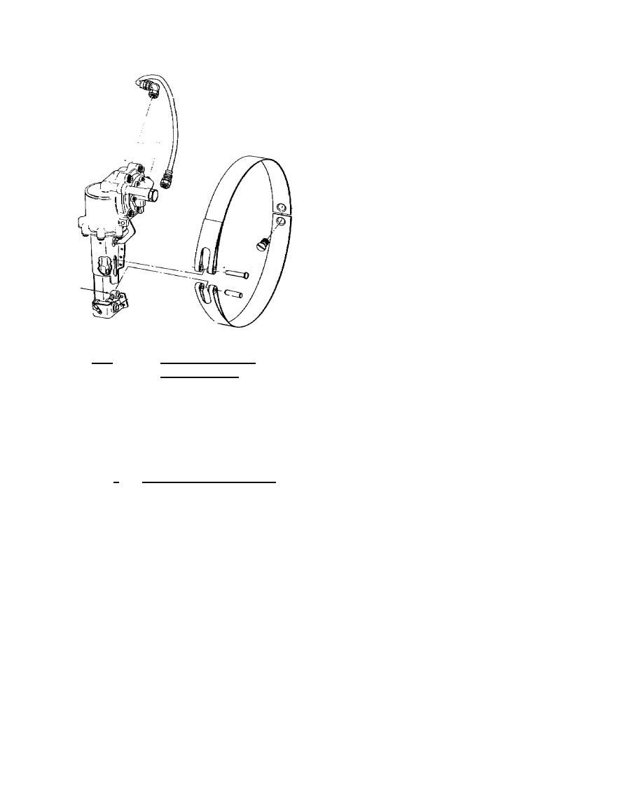
interstage-actuator assembly controls operation of
the air bleed system by tightening or loosening a
metal band over the vent holes in the compressor
housing. The bleed band and actuator assembly
are shown in figure 5.18. The fuel control is
equipped with an acceleration air bleed
adjustment that sets the compressor rotor speed at
which the interstage air bleed closes. This is
usually factory set to close the bleed band at
approximately 30 percent of normal rated power.
5.19.
LUBRICATION SYSTEM
The engine lubrication system has the
dual function of lubricating and cooling. The
principal components of the system are the
integral oil tank, dual element lubrication pump,
filter and screen assemblies, oil cooler assembly,
Figure 5.18.
Interstage Airbleed
oil level indicator assembly, and internal scavenge
Band Assembly.
pumps. The entire lubrication system
is self-contained within the engine. A 3.75-gallon oil tank is located in the engine air inlet housing. The
tank filler neck is located at the top center of the inlet housing. Oil level indication is taken by means of
an externally-mounted mechanical indicator. Two connections, one at the top and one at the bottom of
the tank, are for the addition of an external oil tank to increase the oil capacity. The following
subparagraphs discuss the lubrication system and components.
a.
Oil level indication system. The oil tank has an oil level indicator mounted on the left
side of the inlet housing at the 9-o'clock position and can be read from the top or the side. The
indicator contains a low-level warning switch for remote indication in the cockpit. Based on using the
maximum allowable oil consumption rate, the switch is set to signal when there is a 2-hour supply of
usable oil remaining.
168


 Previous Page
