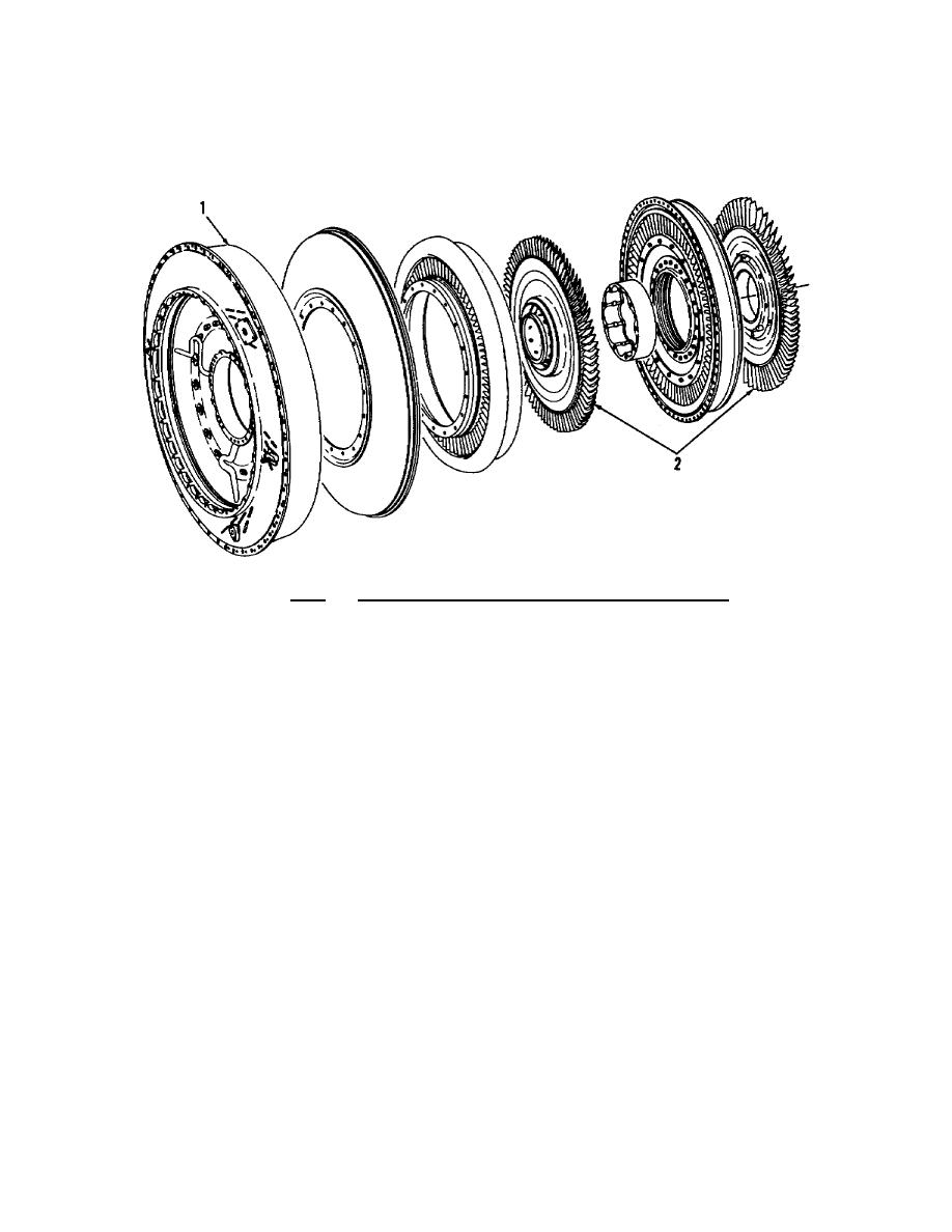
the rear of the Compressor assembly through the No. 2 main bearing.
Also mounted internally, but not a component of the diffuser, are the
combustion chamber deflector curl, first and second stage GP nozzles,
and turbine rotors.
Figure 5.8. Diffuser and Gas Producer Turbine.
5.12.
COMBUSTOR SECTION
The combustion chamber is a reverseflow annular design, which
permits maximum use of space and reduces gas producer and power
turbine shaft length.
The atomizing combustor has 28 main fuel atomizing nozzles.
The nozzles are of the dualorifice design mounted in two
interchangeable, dualchannel, main fuel manifolds, with 14 fuel
nozzles in each manifold.
The perforated combustor liner, shown in figure 5.9, is
manufactured from a heatresistant alloy. The perforations are
arranged to meter air into the combustor for combustion and cooling.
Two combustor drain valves are located at the bottom of the chamber,
to drain raw fuel on engine shutdown after a false or aborted start.
Fuel is injected directly into the combustor through the atomizing
nozzles which are mounted on the fuel manifold at the rear of the
combustor.
156


 Previous Page
