5.6.
DIRECTIONAL REFERENCES AND ENGINE STATIONS
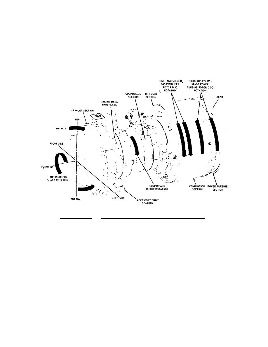
The diagrams in figure 5.4 and 5.5 show directional references
and engine stations. Right and left sides of the engine are
determined by viewing the engine from the rear. Direction of
rotation of the compressor rotor and gas producer turbines is
counterclockwise as viewed from the rear of the engine. The power
turbine and the output gearshaft rotate in a clockwise direction.
Figure 5.4. T55 Engine Directional References.
Engine stations for the T55L11A are shown in figure 5.5. The
compressor housing is station No. 1 starting from the inlet guide
vanes and extending to the centrifugal compressor. Station No. 2
starts at the beginning of the centrifugal compressor and ends at the
air diffuser. Station No. 3 is from the air diffuser exit to the
combustor inlet. Station No. 4 runs from the combustor inlet to the
gas producer (GP) entrance. Station No. 5 is the GP entrance,
station No. 7 is from the GP exit to the PT entrance. Station 7.2 is
the PT entrance, and station No. 9 is the PT exit. No stations are
shown for 6 and 8, because these numbers are not used.
151


 Previous Page
