4.7.
DIRECTIONAL REFERENCES AND ENGINE STATIONS
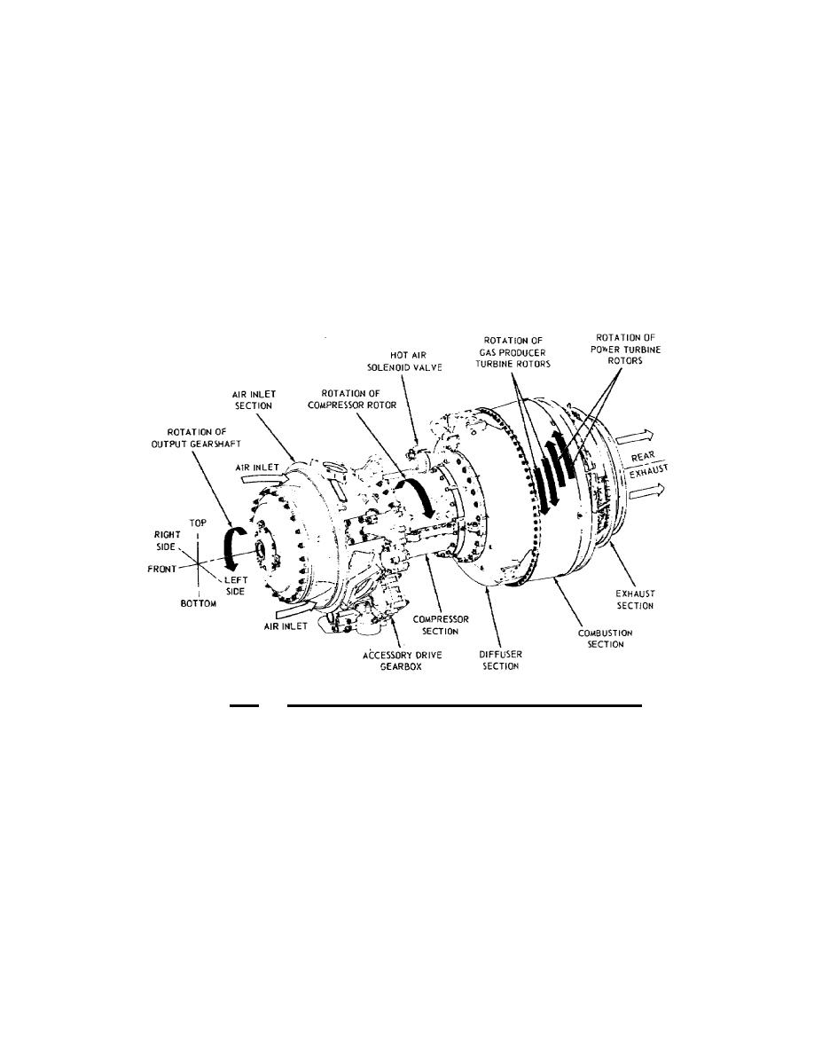
The diagrams in figures 4.3 and 4.4 show directional
references and engine stations. Notice that power output is taken
from the front end and that exhaust gas is expelled from the rear
end. Right and left sides for the engine are determined by viewing
the engine from the rear. The engine's bottom is determined by the
accessory drive gearbox's location. The top of the engine is
directly opposite, or 180 degrees from the accessory drive gearbox.
Rotational direction is determined by viewing from the rear of the
engine. The compressor rotor and gas producer turbines rotate in a
counterclockwise direction. The power turbines and output gearshaft
rotate in a clockwise direction.
Figure 4.3. Engine Orientation Diagram (T53L13).
The T53 engine has 14 ports for test measuring, and it is
divided into stations to designate temperature (T) and pressure (P)
measuring locations. Engine stations for the T53L13 are shown in
Figure 4.4. They are identified on the drawing as 1.0, 2.0, on up to
9.0, but in practice they are spoken of as 1, 2, 3, and so forth.
Station 1, on the inlet housing, is for ambient air. Stations 2 and
3 are for compressor and diffuser discharge air. Station 4 is
located at the combustor section. Stations 5 and 7 designate turbine
No stations are shown for 6 and 8, because these numbers are not used.
97


 Previous Page
