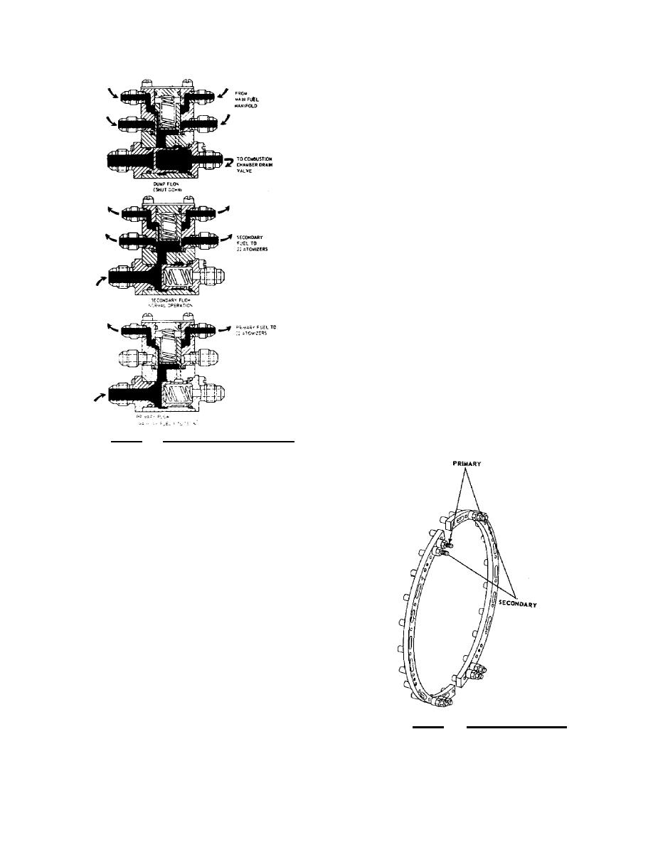
the closed position, allowing
fuel to enter the flow divider
valve. When the inlet pressure
has reached the minimum engine
operating pressure, the dump
valve plunger is in the fully
closed position. The drain valve
seal prevents fuel from the
primary and secondary manifolds
from draining.
Fuel passes the flow
divider series orifice in the
flow divider plunger en route to
the primary manifold, creating a
pressure drop. This pressure
drop across the orifice is
sufficient to move the plunger
off its stop. As the plunger is
displaced, the secondary flow
metering ports in the plunger are
progressively opened, allowing
fuel to pass to the secondary
manifolds. From the flow
divider, fuel flows through
primary and secondary lines to
the main fuel manifold assembly
shown in figure 4.22.
Figure 4.21.
Fuel Flow Divider.
From the flow divider,
fuel flows through primary and
secondary lines to the main fuel
manifold assembly. The manifold
is a twosection, dualchanneled
assembly with eleven outlets in
each section. Each manifold half
is interchangeable, requiring
only a minor hardware adjustment
to make the change. The 22 fuel
atomizers are attached directly
to the manifolds, which discharge
the atomized fuel into the
The fuel atomizer, as
shown in figure 4. 23 is a dual
orifice injector designed to
accommodate the separate primary
and secondary fuel flow
functions. The separate orifices
Figure 4.22. Fuel Manifold.
spray
119


 Previous Page
