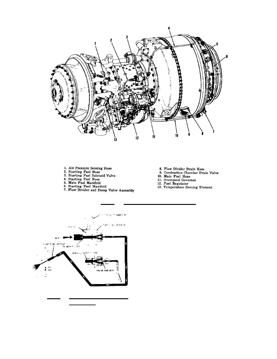
Figure 4.19. Fuel System Components.
(54 C) to 200 F (93 C). The
flow divider assembly, shown in
figure 4.21 has a lower housing
containing the dump valve and an
upper housing for the flow
divider. These housings are
machined from corrosion resistant
steel casting, and sharp edges
are maintained on all metering
slots and ports.
When fuel pressure at
the inlet reaches a predetermined
value, the dump valve plunger
Figure 4.20.
Starting Fuel Flow
moves toward
Sequence.
118


 Previous Page
