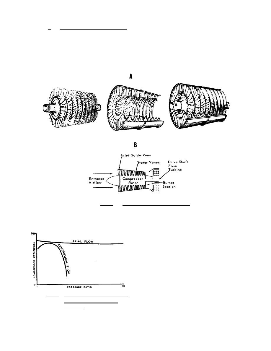
b. Axialflow compressor. The air is compressed, as the name
implies, in a direction parallel to the axis of the engine. The
compressor is made of a series of rotating airfoils called rotor
blades, and a stationary set of airfoils called stator vanes. A
stage consists of two rows of blades, one rotating and one
stationary. The entire compressor is made up of a series of
alternating rotor and stator vane stages as shown in figure 1.13.
Figure 1.13. Axialflow Compressor.
Axial flow compressors have the advantage of being capable
of very high compression ratios with relatively high efficiencies;
see figure 1.14. Because of the
small frontal area created by
this type of compressor, it is
ideal for installation on high
speed aircraft. Unfortunately,
the delicate blading and close
tolerances, especially toward the
rear of the compressor where the
blades are smaller and more
numerous per stage, make this
compressor highly susceptible to
Figure 1.14. Compressor Efficien
foreignobject damage. Because
cies and Pressure
of the close fits required
Ratios.


 Previous Page
