attack, the result is a slight but important forward inclination of aerodynamic force. This inclination
supplies thrust slightly ahead of the rotating axis and tends to speed up this portion of the blade during
autorotation.
The blade area outboard of the 70 percent circle is known as the propeller or driven region. Analysis
of blade element B in figure 3.13 shows that the aerodynamic force inclines slightly behind the rotating
axis. This inclination causes a small drag force that tends to slow the tip portion of the blade. Rotor rpm
stabilizes, or achieves equilibrium, when autorotative force and antiautorotative force are equal.
The blade area inboard of the 25 percent circle is known as the stall region because it operates above
its maximum angle of attack. This region contributes considerable drag that tends to slow the blade.
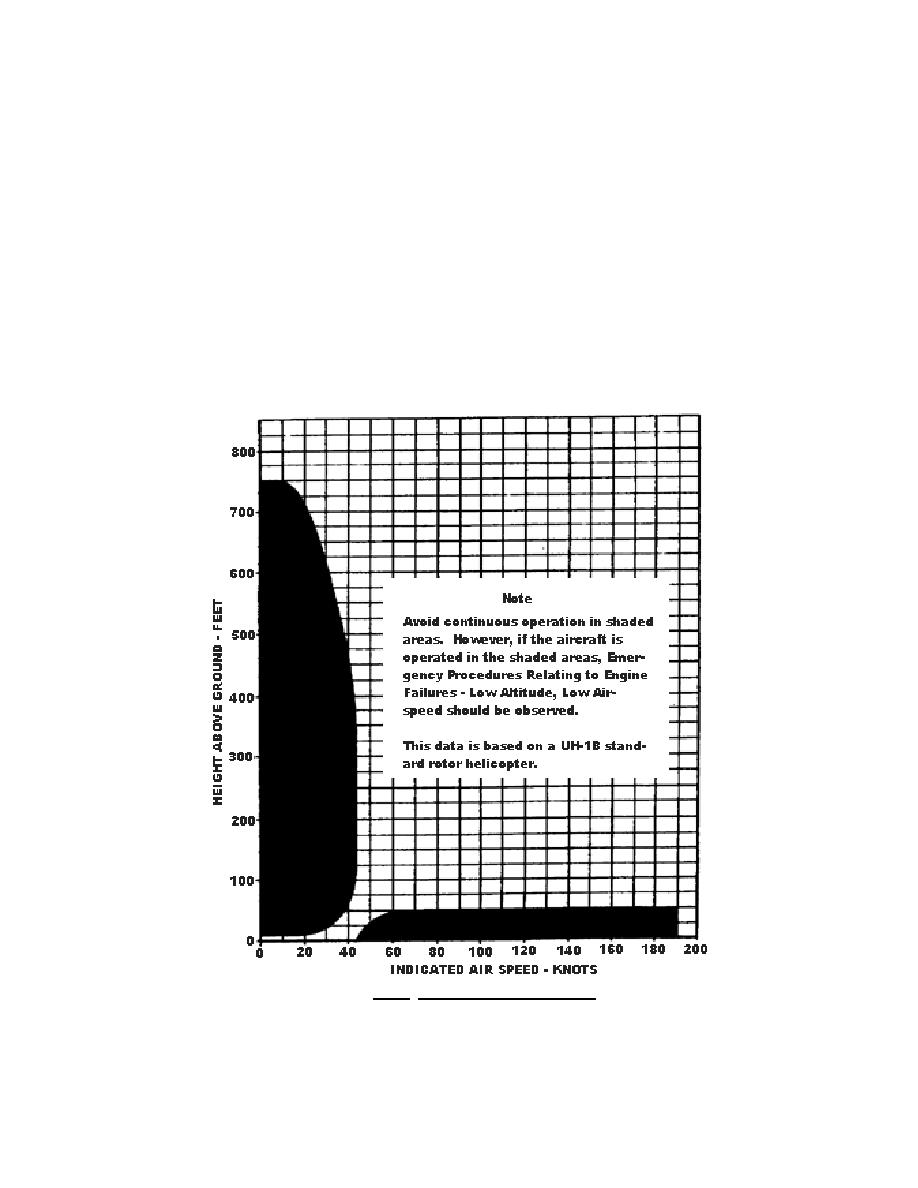
All helicopters carry an operators manual (-10) that has an air speed versus altitude chart similar to
the one shown in figure 3.14. The shaded areas on this chart must be avoided. The proper maneuvers
for a safe landing during engine failure cannot be accomplished in these areas.
Figure 3.14. High Velocity Diagram.
32


 Previous Page
