charge, filling the upper chamber with fluid pressure. The broken lines in Figure 1-11 indicate the
approximate position of the bladder at the time of the initial air charge.
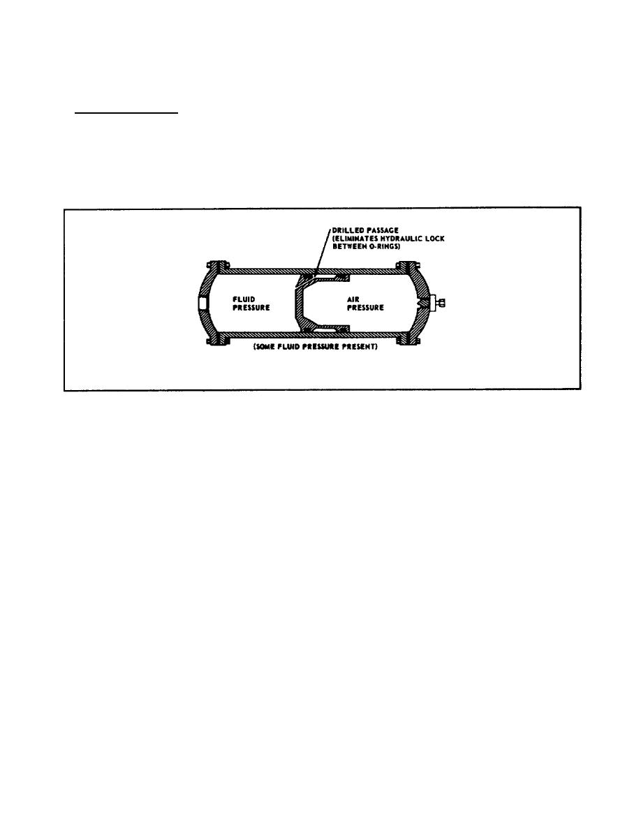
Piston Accumulator. The piston accumulator serves the same purpose and operates by the same
principles as do the diaphragm and bladder accumulators. As shown in Figure 1-12, the unit consists of
a cylinder and piston assembly with ports on each end. Fluid pressure from the system enters the left
port, forcing the piston down against the initial air charge in the right chamber of the cylinder. A high-
pressure air valve is located at the right port for charging the unit. A drilled passage from the fluid side
of the piston to the outside of the piston provides lubrication between the cylinder walls and the piston.
Figure 1-12. Piston Accumulator.
HYDRAULIC MOTORS
Hydraulic motors are installed in hydraulic systems to use hydraulic pressure in obtaining powered
rotation. A hydraulic motor does just the opposite of what a power-driven pump does. A pump receives
rotative force from an engine or other driving unit and converts it into hydraulic pressure. A hydraulic
motor receives hydraulic fluid pressure and converts it into rotative force.
Figure 1-13 shows a typical hydraulic motor. The two main ports through which fluid pressure is
received and return fluid is discharged are marked A and B, respectively. The motor has a cylinder
block-and-piston assembly in which the bores and pistons are in axial arrangement, the same as in a
hydraulic pump. Hydraulic motors can be instantly started, stopped, or reversed under any degree of
load; they can be stalled by
16
AL0926


 Previous Page
