
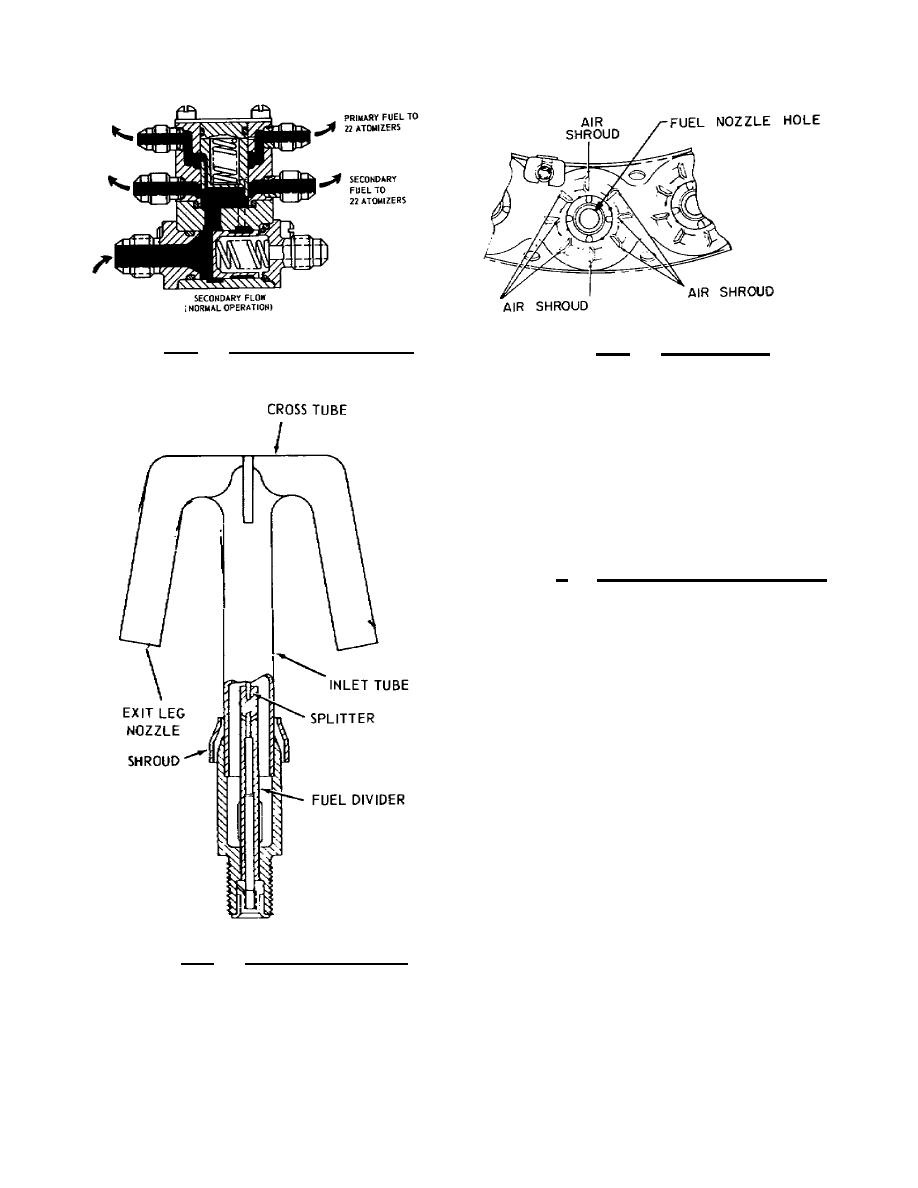
Figure 2.6. Fuel Flow Divider.
Figure 2.7. Air Shroud.
A word of caution;
extreme care must be taken when
cleaning or handling the nozzles,
since even the acid on the
fingers may corrode and produce a
spray pattern which is out of
tolerance.
c. Vaporizing
tube.
Engines such as the Lycoming T53
L11 use vaporizing tubes instead
of injector nozzles. The
vaporizing tube is a Tshaped,
ceramiccoated pipe, whose exit
faces upstream to the airflow.
Figure 2.8 shows a vaporizing
tube that is used on the T53L
ll.
2.8.
Gas turbine engines may
have several fuel filters
installed at various points
throughout the systems, one fuel
filter before the fuel pump and
one on the highpressure side
Figure 2.8. Vaporizing Tube.
after the pump. In most cases
the filter includes a relief
valve set to open at a specified differential pressure (PSID) between
inlet and outlet pressure. This gives the fuel a bypass if the
filter becomes clogged from contamination.


 Previous Page
