gear drives the accessory section. The accessory drive assembly consists of accessory gears and the
intermediate gear. These gears drive the hydraulic starter, the fuel control, and a speed switch and
tachometer generator.
6.6.
COMBUSTOR ASSEMBLY
The annular combustor assembly consists of a housing, liner, and nozzle shield, items 15
through 17 in figure 6.3. The assembly is secured to the turbine housing by a V-clamp, item 19 in the
figure. Six self-tapping screws support and center the liner in the housing. Fuel for the combustor is
supplied by six equally spaced fuel vaporizers connected by a circular manifold on the combustor
housing. A combustion chamber drain valve is installed at the 6 o'clock position on the combustion
housing.
6.7.
TURBINE ASSEMBLY
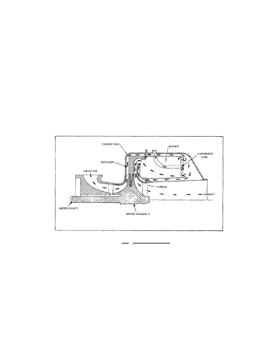
The turbine assembly consists of the rotor, air inlet, diffuser, and nozzle assemblies. These
items are shown in the airflow diagram in figure 6.5.
Figure 6.5. Airflow Diagram.
The centrifugal compressor rotor and radial inflow turbine rotor are bolted to the aft end of
the rotor shaft. A single forward ball bearing and an aft roller bearing support the shaft. These are
items 8 and 9 in figure 6.3 and 6.4. The air inlet assembly serves
181


 Previous Page
