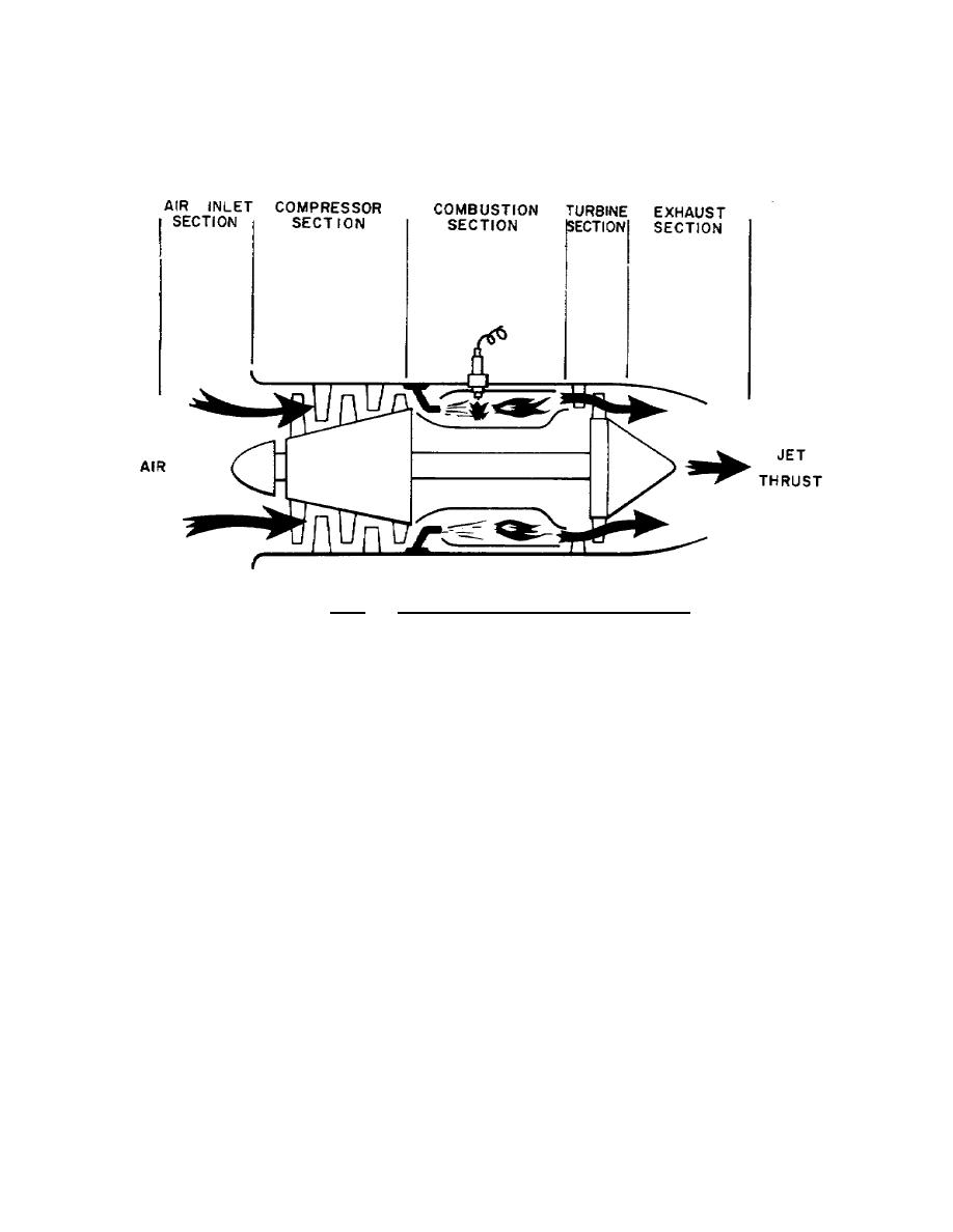
wheel to sustain operation of the compressor. The remaining energy
is discharged from the rear of the engine as a high velocity jet, the
reaction to which is thrust or forward movement of the engine. The
turbojet is shown schematically in figure 1.3.
Figure 1.3. AxialFlow Turbojet Engine.
1.11.
TURBOPROP ENGINE AND TURBOSHAFT ENGINE
The turboprop engine and turboshaft engines, shown in figures
1.4 and 1.5, are of the same basic type as the turbojet. Instead of
ejecting highvelocity exhaust gases to obtain thrust, as in the
turbojet, a turbine rotor converts the energy of the expanding gases
to rotational shaft power. A propeller or helicopter transmission
can be connected to the engine through reduction gearing. This
energy may be extracted by the same turbine rotor that drives the
compressor, or it may be a freepower turbine which is independent of
the compressor turbine and only linked to it by the expanding gases.
The freepower turbine is the type used in Army aircraft to
harness the energy of the gases and convert this energy to rotational
shaft power. This feature of having a freepower turbine enables the
power output shaft to turn at a constant speed while the power
producing capability of the engine can be varied to accommodate the
increased loads applied to the power output shaft. Turbine engines
may be further divided into three general groups, centrifugalflow,
axialflow, and axialcentrifugalflow, depending upon the type of
15


 Previous Page
