increase in air pressure; combined they constitute one stage of
compression. This action continues through all stages of the axial
compressor. To retain this pressure buildup, the airflow is
delivered, stage by stage, into a continually narrowing airflow path.
After passing from the last set of stator vanes the air mass passes
through exit guide vanes. These vanes direct the air onto the
centrifugal impeller.
The centrifugal impeller increases the velocity of the air
mass as it moves it in a radial direction. The axialcentrifugal
flow compressor is discussed further in chapter 4.
d. Compressor stall. Gas turbine engines are designed to
avoid the pressure conditions that allow engine surge to develop, but
the possibility of surge still exists in engines that are improperly
adjusted or have been abused. Engine surge occurs any time the
combustion chamber pressure exceeds that in the diffuser, and it is
identified by a popping sound which is issued from the inlet.
Because there is more than one cause for surge, the resultant sound
can range from a single carburetor backfire pop to a machinegun sound.
Engine surge is caused by
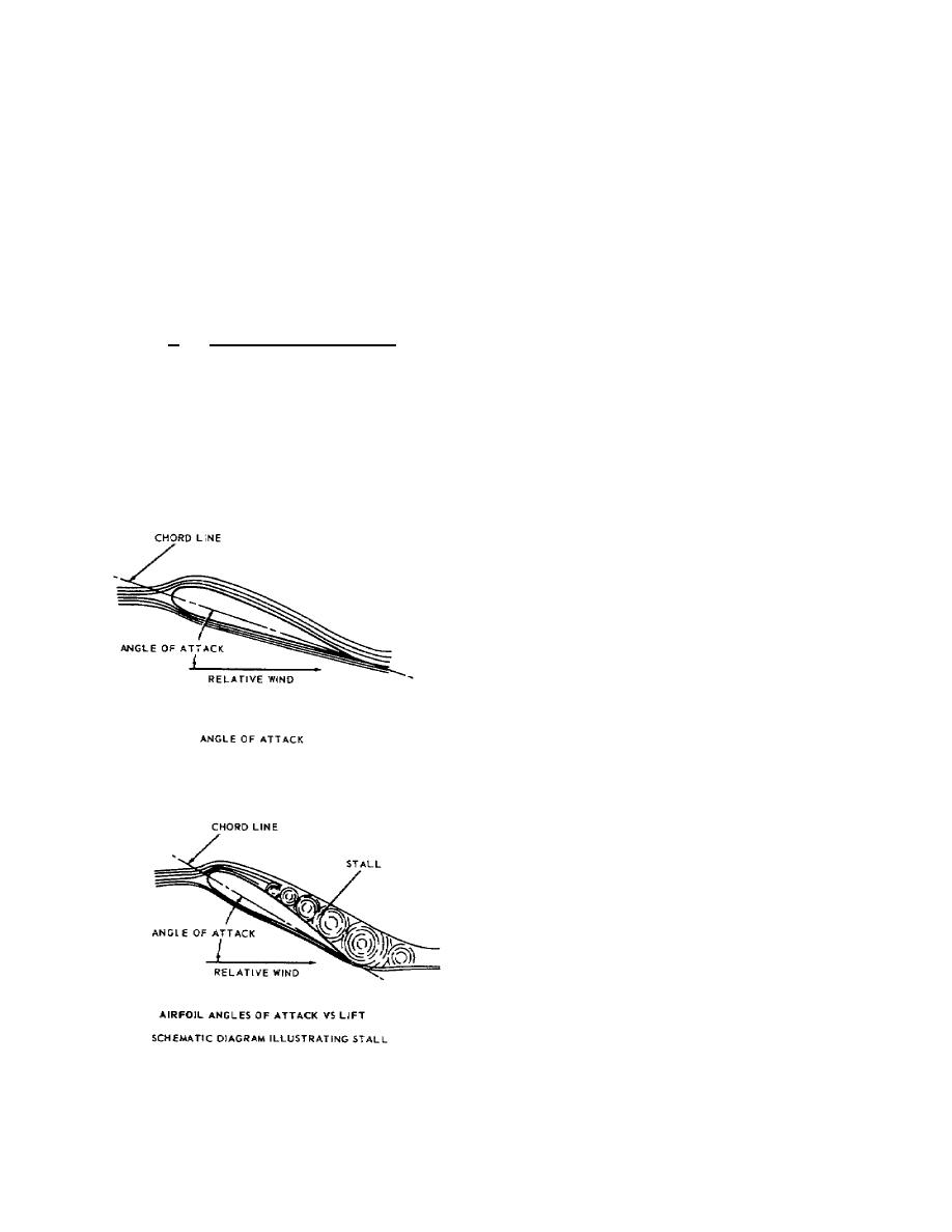
a stall on the airfoil surfaces
of the rotating blades or
stationary vanes of the
compressor. The stall can occur
on individual blades or vanes or,
simultaneously, on groups of
them. To understand how this can
induce engine surge, the causes
and effects of stall on any
airfoil must be examined.
All airfoils are designed
to provide lift by producing a
lower pressure on the convex
(suction) side of the airfoil
than on the concave (pressure)
side. A characteristic of any
airfoil is that lift increases
with an increasing angle of
attack, but only up to a critical
angle. Beyond this critical
angle of attack, lift falls off
rapidly. This is due largely to
the separation of the airflow
from the suction surface of the
airfoil, as shown in the sketch.
This phenomenon
32


 Previous Page
